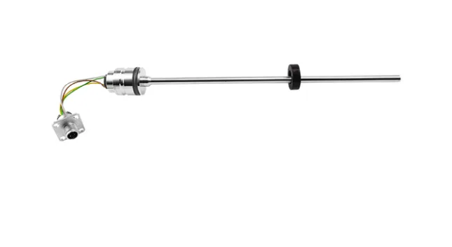
SEGMENsensor LVDT gauging probe sensors are precision displacement transducers designed for automated dimensional measurement, 100% in-process inspection, and coordinate gauging fixtures. The hardened probe tip (ruby ball, carbide, or flat) rides directly on the workpiece surface. Stroke 5–50 mm. Linearity ±0.05% FS. AC LVDT output or integrated 4-20mA/0-10V signal conditioner. Stainless steel housing. CE certified. OEM from Shenzhen since 2019, MOQ 10 pcs.
An LVDT gauging probe sensor is a Linear Variable Differential Transformer packaged as a precision measurement probe for contact dimensional gauging applications. Unlike position measurement LVDTs that couple the core to a moving machine part, a gauging probe LVDT has an exposed probe tip (ruby, carbide, or flat steel) on the extending rod that directly contacts the part surface being measured. The probe tip displacement drives the LVDT core, producing a voltage (AC) or conditioned current (4-20mA) signal proportional to the dimension. Gauging LVDTs are the reference-grade sensors in automated gauging fixtures, post-process inspection cells, and inline quality control systems for precision machined components.
Specifications
LVDT Gauging Probe Sensor — Full Specification Table
Standard and reference-grade configurations. AC LVDT and DC conditioned (4-20mA / 0-10V) output options. All models CE and RoHS certified.
Three output and grade options to match your measurement system, PLC architecture, and tolerance requirements.
⚡AC LVDT Version
Connects to a dedicated LVDT signal conditioning card or measurement amplifier
Highest possible resolution — limited only by the signal processing chain, not the sensor
Ideal for high-precision coordinate measurement benches and metrology instruments
Pure analog signal path with no embedded electronics — lowest sensor thermal error
→ Best for metrology instruments & CMM fixtures
🔌DC 4-20mA Version
Direct connection to PLC / DCS analog input — plug-and-play integration
No external signal conditioner required — embedded demodulator inside the housing
Ideal for in-line production inspection stations and automated gauging fixtures
24V DC loop powered, 2-wire wiring, standard industrial connection
→ Best for PLC-based production line gauging
🏆Reference Grade ±0.02% FS
±0.02% FS linearity with active temperature compensation
Supplied with NIST-traceable calibration certificate and calibration data file
Suitable for metrology laboratory, sampling inspection stations, and certified test measurement
5–6 week lead time; available in AC and DC output versions
→ Best for metrology labs & certified inspection
Applications
LVDT Gauging Probe Applications in Precision Manufacturing
From automotive engine components to aerospace turbine blades — LVDT gauging probes deliver reference-grade dimensional measurement across industries.
⚙️
Engine Component Gauging
Bore diameter, step height, and runout on crankshafts, camshafts, and pistons in engine assembly quality control lines.
✈️
Turbine Blade Inspection
Airfoil thickness and profile measurement in aerospace inspection fixtures for high-pressure turbine and compressor blades.
🔩
Bearing Inner/Outer Race
Wall thickness and raceway profile measurement in bearing production lines — critical for noise and fatigue life control.
⚡
Gear Tooth Profile
Tooth spacing and involute profile gauging in gear hobbing quality control — detects pitch error and profile deviation.
🖥️
PCB Flatness Testing
Board warpage and component height measurement in SMT assembly — identifies boards outside bow/twist specification.
🦴
Orthopedic Implant
Hip stem taper, acetabular cup diameter — precision gauging in medical device manufacturing to ISO 13485 requirements.
🏎️
Automotive Cylinder
Liner bore diameter, piston ring gap measurement in engine assembly — 100% in-process gauging at production line rate.
🏭
Die Casting Flash
Part thickness at parting line for flash detection and reject sorting — replaces manual inspection with automated gauging fixture.
How to Use
How to Use an LVDT Gauging Probe in a Production Fixture
Three steps from fixture installation to automated accept/reject output in a production gauging cell.
01
Mount & Align
Install the gauging probe sensor in the fixture or measurement stand using M8/M12 thread. The probe axis must be perpendicular to the surface being measured. Contact force is controlled by the spring-loaded version (0.3–1 N) or by fixture depth stop. Ensure probe stroke mid-point aligns with the nominal part dimension (null zone).
02
Zero Calibration
Place a gauge block or reference master part at nominal dimension under the probe. Zero the signal conditioner output (for AC: null voltage; for 4-20mA: 12mA = mid-stroke). Record this physical position as the measurement datum. Repeat zero calibration at the start of each production shift and after thermal stabilisation.
03
Measure & Reject
Load the workpiece into the fixture. The probe tip contacts the measured surface and reads the dimensional deviation from nominal. The PLC reads the analog signal and compares against the ±tolerance band. OK/NG digital outputs trigger part sorting — pass or reject — without operator intervention. Cycle time typically 0.5–2 seconds per part.
Why SEGMENsensor
OEM LVDT Gauging Probe Factory — Verified Quality
Every LVDT gauging probe ships with factory calibration data, CE declaration, and RoHS compliance certificate.
Technical and sourcing questions from OEM buyers and quality engineers about LVDT gauging probe sensors.
What is the difference between an LVDT gauging probe and a standard LVDT position sensor?
A standard LVDT position sensor has the core mechanically coupled (attached) to the moving part of the machine — it measures machine displacement. An LVDT gauging probe has a free, exposed probe tip that contacts a part surface to measure its geometry — the core follows the probe tip by spring contact or free sliding. Gauging probes are built to tighter linearity specifications (±0.02–0.05% FS vs ±0.1% FS) and use precision hardened probe tips to ensure repeatable contact. The housing is machined to close dimensional tolerances for press-fit or threaded installation in gauge bodies and CMM-style fixtures.
What probe tip material should I choose for my gauging application?
Ruby ball (aluminium oxide): hardest natural material after diamond, excellent wear resistance, ideal for ferrous and non-ferrous workpieces, widely used in automated gauging — recommended as the default. Tungsten carbide ball: harder than steel, resists abrasion from cast iron, sintered parts, or abrasive workpieces. Flat disc tip: for measuring into grooves, chamfers, or against shoulders where a ball tip would fall into the geometry. Needle point: for surface tracing, fine groove measurement, and deep bore probing. SEGMENsensor supplies all four options in 1 mm and 2 mm contact diameters.
What linearity specification do I need for production gauging?
For production inspection with tolerances ≥±0.05 mm: standard ±0.05% FS (on a 10 mm stroke = ±5 µm linearity) is more than sufficient. For tolerances of ±0.02–0.05 mm: use ±0.05% FS with careful zero calibration and temperature control. For tolerances <±0.02 mm: use the ±0.02% FS reference-grade version with NIST-traceable calibration. As a rule: the gauging sensor's linearity error should be less than 10% of your part tolerance. Calibrate the zero reference at the beginning of each production shift.
How do I connect an LVDT gauging probe to a PLC analog input?
If using the DC conditioned version (4-20mA output): wire as a standard 2-wire loop-powered transmitter — Brown (+) to PLC analog input positive, Blue (–) to PLC analog input negative, with 24V DC loop supply. Set PLC scaling: 4mA = minimum stroke (fully retracted), 20mA = maximum stroke (fully extended). If using raw AC LVDT output: you need an LVDT signal conditioner (demodulator) between the sensor and the PLC. The conditioner provides the AC excitation and converts the AC differential output to a DC voltage or 4-20mA. SEGMENsensor recommends the DC conditioned version for direct PLC integration.
What is the contact force of an LVDT gauging probe and does it affect measurement accuracy?
The free-probe (unconstrained) version has no spring — probe contact force is determined entirely by the fixture design (typically 0.1–0.5 N from a light fixture clamp or gravity). The spring-loaded version applies 0.3–1.0 N (adjustable) to maintain positive contact. Contact force affects measurement only if it deflects the workpiece (thin-wall parts, PCBs). For rigid machined parts, the force is irrelevant. For soft or thin parts (<0.5 mm sheet), use the free-probe version with gravity or fixture contact. In automated gauging cells, the part is loaded and clamped before probing — the probe contact force is usually less than 0.5 N, causing negligible part deflection.
What is LVDT gauging probe null position and how do I set it?
The null position is the electrical zero point — the probe location where the LVDT differential output is zero volts (for AC output) or 12mA (for 4-20mA output, corresponding to mid-stroke). For gauging, the null is not usually at zero but at the nominal dimension: place a calibration standard (gauge block at nominal size) under the probe, then zero the signal conditioner's offset to read 0V or 12mA. Now all deviations from nominal register as + (oversize) or – (undersize). The LVDT's linearity and drift are minimized near null, so design your gauge fixture to operate within ±20% of stroke around the null point for best accuracy.
Can LVDT gauging probes be used in wet or coolant environments?
Standard LVDT gauging probes are rated IP54 (splash-resistant) — suitable for coolant mist environments in CNC cells. For direct coolant spray or parts washing environments, specify the IP67 sealed version with stainless steel housing and sealed probe rod bearing. The probe tip (ruby or carbide) is unaffected by coolant or water. For food-grade or pharmaceutical applications requiring washdown with cleaning agents, use the all-stainless 316L housing with PTFE-sealed probe exit. The probe rod bearing material should be confirmed compatible with the cleaning agent.
What is the MOQ and lead time for LVDT gauging probe sensors from a China factory?
MOQ 10 pcs for standard LVDT gauging probe sensors (stroke 5, 10, 25 mm; 4-20mA DC output; M12 connector; ruby ball tip). Sample 1–2 pcs accepted. Standard lead time: 3–4 weeks. Custom configurations (reference grade ±0.02% FS, AC output, non-standard stroke, carbide/flat/needle tip, IP67, NIST calibration certificate, OEM label): add 2–3 weeks. CE declaration of conformity and factory calibration report included. Factory: Segmen Industrial Development Co., Ltd., Registration No. 91440300MAEUXXQU04, Shenzhen, Guangdong, China.
Ready to Source LVDT Gauging Probe Sensors from a China OEM Factory?
Tell us your stroke, required linearity, probe tip type, and output signal — we'll send a quote, datasheet, and fixture integration note within 24 hours.