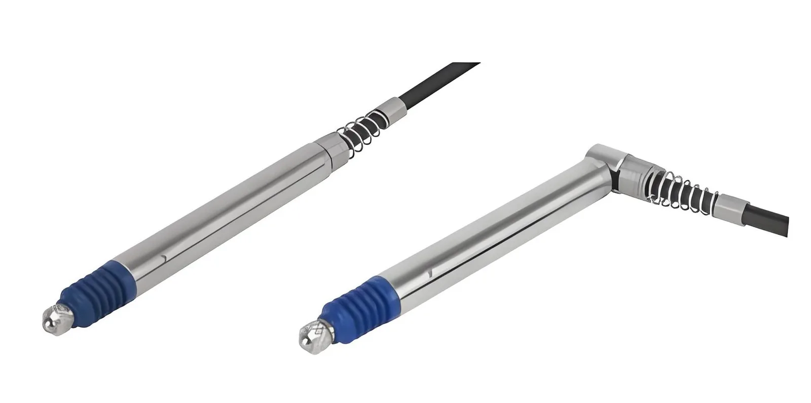
An LVDT cannot drive a PLC input on its own: it needs an AC excitation and a demodulator that turns the small AC difference signal into a DC value. That circuit is the signal conditioner. With an AC LVDT it is a separate module wired between sensor and controller; with a DC LVDT it is built into the sensor body, so the cable already carries 4–20 mA, 0–10 V or RS485.
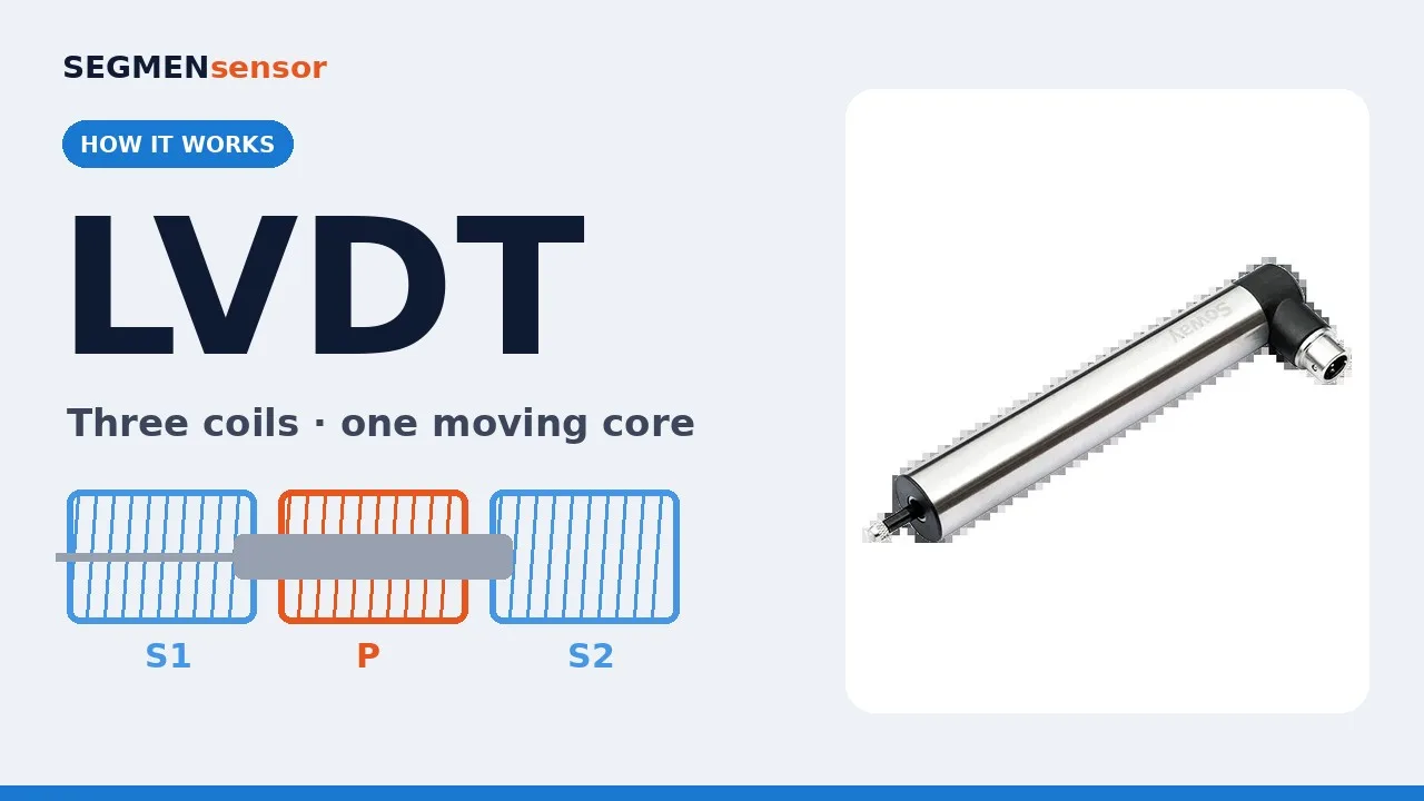
A linear variable differential transformer has one primary coil, two secondary coils and a moving core. Nothing in that coil set produces a usable signal until the primary is excited with AC and the two secondary voltages are compared. This guide explains what the conditioning electronics do, how AC and DC LVDTs split that job, how to scale the output, and what to send when you request a quote. The figures below come from the SEGMENsensor LVDT displacement sensor product page and datasheet. For the transducer itself, see what an LVDT sensor is.
What Does an LVDT Signal Conditioner Do?
It performs three jobs: it excites the primary coil, it demodulates the secondary signal, and it converts the result into a standard output. Without those three steps the LVDT output is an AC voltage whose amplitude shows how far the core has moved and whose phase shows the direction, which no ordinary analog input can read.
- Excitation: a stable sine wave drives the primary coil. SEGMENsensor AC-type LVDTs are specified for 1–10 kHz and 1–5 Vrms.
- Demodulation: a phase-sensitive (synchronous) demodulator compares the secondary difference signal with the excitation, so the DC result is positive on one side of the null point and negative on the other.
- Output stage: filtering, zero and span adjustment, then a 4–20 mA, 0–10 V, ±10 V or RS485 Modbus RTU output.
How it works, step by step
- The conditioner drives the primary coil with an AC excitation of 1–10 kHz.
- The core position changes the coupling into the two secondaries, and the conditioner demodulates their difference against the excitation phase.
- The demodulated DC value is filtered, scaled and output as 4–20 mA, 0–10 V, ±10 V or an RS485 Modbus RTU register.
AC LVDT vs DC LVDT: Where Does the Conditioner Sit?
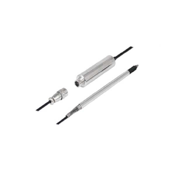
The difference between an AC and a DC LVDT is only where the conditioning electronics are. An AC LVDT is the bare coil set, and the conditioner is a separate module or a card in the controller. A DC LVDT has the conditioner inside the housing, so it is powered from DC and outputs a standard signal. The table compares the two on SEGMENsensor's published specifications.
| Item | AC LVDT + external conditioner | DC LVDT (built-in conditioner) |
|---|---|---|
| Supply to the sensor | AC excitation, 1–10 kHz, 1–5 Vrms, from the conditioner | DC supply through a built-in DC-DC converter (range per model on the datasheet) |
| Signal on the sensor cable | Low-level AC differential signal | 4–20 mA, 0–10 V, ±10 V or RS485 Modbus RTU |
| Typical SEGMENsensor series | SDVH gauging probes (±0.5 to ±5 mm), SDVG separate-core (±2 to ±100 mm) in AC versions | SDVH and SDVG DC versions; SLT pen-type (±10 to ±500 mm) |
| Resolution | Infinite in principle; limited by the conditioner | Infinite (analog); 0.001 mm on SLT RS485 |
| Temperature at the sensor | Coil set only at the measuring point; SDVH and SDVG rated -40 to +125 °C | Electronics sit at the measuring point with the coil set |
| Best fit | Hot or tight locations, multi-channel gauging, existing LVDT conditioner cards | Single-cable connection to a PLC, press, test rig or machine axis |
Choose an AC LVDT when the measuring point is hot or cramped and the electronics are better placed in a cabinet, or when a multi-channel gauging system already has conditioner channels. Choose a DC LVDT when you want one cable from the sensor straight to a PLC analog input or a Modbus master, which is how most press, test-rig and machine-tool axes are wired.
Which Output Should You Choose: 4–20 mA, 0–10 V or RS485?
Choose 4–20 mA for long cable runs and noisy machines, 0–10 V or ±10 V for short runs into controllers that expect voltage, and RS485 Modbus RTU when you need a digital reading or several sensors on one bus. The 4–20 mA current loop is defined in IEC 60381-1 — analogue direct current signals for process control systems ↗; its live zero at 4 mA lets the controller tell a broken wire from a real reading. RS485 wiring and register reading are covered in RS485 Modbus RTU sensors.
Scaling a bipolar LVDT stroke is straightforward. On a ±100 mm SDVG separate-core LVDT with 4–20 mA output, the null point reads 12 mA, -100 mm reads 4 mA and +100 mm reads 20 mA. The slope is 16 mA over 200 mm, or 0.08 mA per mm (calculated value). On a ±10 V output the same stroke gives 0.1 V per mm (calculated value), with 0 V at the null point.
| Output | Null point (±100 mm stroke) | Full stroke reading | Sensitivity (calculated) |
|---|---|---|---|
| 4–20 mA | 12 mA | 4 mA at -100 mm, 20 mA at +100 mm | 0.08 mA/mm |
| 0–10 V | 5 V | 0 V at -100 mm, 10 V at +100 mm | 0.05 V/mm |
| ±10 V | 0 V | -10 V at -100 mm, +10 V at +100 mm | 0.1 V/mm |
| RS485 Modbus RTU (SLT) | Register value at zero | Position in mm from the register | 0.001 mm resolution |
- AC excitation: 1–10 kHz, 1–5 Vrms (AC-type SDVH and SDVG).
- Conditioned outputs: 4–20 mA, 0–10 V, ±10 V, RS485 Modbus RTU; AC differential for external conditioners.
- Stroke: ±0.5 to ±5 mm (SDVH), ±2 to ±100 mm (SDVG), ±10 to ±500 mm (SLT); 1 mm = 0.0394 in.
- Linearity: ±0.1% FS (SDVH), ±0.25% FS standard; repeatability ±0.01% FS.
- Environment: IP67; SDVH and SDVG -40 to +125 °C.
Download the one-page datasheet (PDF)
The LVDT displacement sensor datasheet lists stroke ranges, linearity, excitation, output options, supply voltage, temperature limits, IP rating, dimensions and the ordering code. No registration required.
Need an LVDT with the right electronics for your machine?
Send stroke, output, supply, temperature and cable length, and say whether the conditioner should be built in or external. Qualification samples 1–5 pcs in 5–7 working days · production planned around your annual volume · reply within 24 hours.
Does the Signal Conditioner Change LVDT Accuracy?
Yes, the conditioner adds its own error, so the system accuracy is the transducer and the electronics together. The transducer sets the linearity (±0.1% FS on SDVH probes, ±0.25% FS on standard models), and the conditioner adds gain drift, offset and noise. Calibrate the LVDT and its conditioner as a pair, and keep that pairing in service. Performance evaluation methods for industrial process transmitters are set out in IEC 60770-1 — transmitters for industrial-process control: methods for performance evaluation ↗. A DC LVDT is calibrated with its built-in electronics at the factory, which removes the pairing step.
How Do You Wire and Set Up an LVDT Conditioner?
- Cable: use shielded cable and ground the shield at one end; on AC LVDTs keep the low-level secondary wires away from motor and valve cables.
- Null point: mount the core so the mechanical mid-stroke matches the electrical null (12 mA, 5 V or 0 V in the table above) before tightening.
- Zero and span: set zero at one end of the working stroke and span at the other, then check the mid-point reading.
- Units: record the scaling in millimetres in the controller. The NIST SI units reference ↗ gives the base unit definitions used for length conversions.
For long strokes in hydraulic cylinders, a magnetostrictive sensor is often the better choice; the trade-offs are compared in LVDT vs magnetostrictive sensor. For spring-return probes on inspection fixtures, see the spring-loaded LVDT sensor.
Factory-Direct LVDT Supply for OEMs
SEGMEN (Shenzhen) Industrial Development Co., Ltd. was founded in Shenzhen in 2019; its engineering team brings more than 20 years of sensor experience and supplies 200+ OEM customers in 30+ countries. LVDTs are built on an ISO 9001:2015 production line with a monthly capacity of 50,000 units. Stroke, output, connector and housing are configured per project, and customised samples take 7–14 days. Quotations are FOB China with 100% T/T in advance, and the warranty is 12 months.
Frequently Asked Questions
It excites the LVDT primary coil with AC, demodulates the secondary difference signal into a DC value, and outputs it as 4–20 mA, 0–10 V, ±10 V or RS485 Modbus RTU.
No. A DC LVDT has the conditioner built into its housing, so it runs from a DC supply and outputs a standard signal directly. Only AC LVDTs need an external conditioner.
SEGMENsensor AC-type LVDTs are specified for 1–10 kHz excitation at 1–5 Vrms. Match the conditioner's excitation to the value on the LVDT datasheet.
4–20 mA is the usual choice for long or noisy cable runs, 0–10 V suits short runs into voltage inputs, and RS485 Modbus RTU gives a digital reading with 0.001 mm resolution on SLT pen-type LVDTs.
Yes. The transducer sets the linearity, ±0.1% FS on SDVH probes and ±0.25% FS on standard models, and the conditioner adds gain drift, offset and noise, so calibrate the LVDT and conditioner as a pair.
Related reading: LVDT displacement sensors — product page · Spring-loaded LVDT sensor · What is an LVDT sensor? · LVDT vs magnetostrictive sensor · RS485 Modbus RTU sensors
Last updated: 23 October 2026. Specifications reflect the SEGMENsensor LVDT product page and datasheet at the time of writing; calculated values are marked as such.