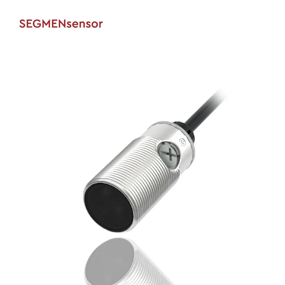
A through-beam pair puts the emitter and receiver on opposite sides of the gap, so the target simply breaks the beam. It is the most reliable optical sensing mode in dust, mist and vibration, and the only one that reaches 40 m. Available in M8 stainless, M12, M18 and M30 barrels and two rectangular sizes, with NPN or PNP outputs and IP67 protection.
Reviewed by the SEGMENsensor applications engineering team · Shenzhen, ChinaSpecifications taken from current production selection tablesLast updated:
What is a through-beam photoelectric sensor?
A through-beam photoelectric sensor uses a separate emitter and receiver mounted opposite each
other. The emitter sends a continuous modulated beam; the receiver switches its output the moment a
target interrupts that beam. Because the light crosses the gap only once, this arrangement delivers
the highest signal margin and the longest range of any optical sensing mode.
Emitter and receiver face each other. The output switches when the target breaks the beam.
When should you choose through-beam over the other modes?
Choose through-beam whenever detection reliability matters more than installation effort. Four
situations make it the clear answer:
Long spans. Ranges beyond 6 m rule out diffuse optics entirely.
Dust, mist or spray. The high excess gain tolerates lens contamination that
would blind a diffuse sensor within a shift.
Dark, matt or irregular targets. Detection depends on blocking light, not on
reflecting it, so target colour barely matters.
Vibration-prone frames. A strong beam tolerates the small alignment drift that
a long conveyor structure produces.
The trade-off is installation: two housings, two mounting points and a cable run on each side.
What ranges are available?
Barrel and rectangular through-beam pairs cover 80 mm to 40 m. Slot sensors, which are
also a through-beam arrangement, cover fixed gaps from 5 mm to 50 mm and are described on
the slot sensor page.
Housing
Series
Rated range
Typical application
M8 stainless barrel
SEGS8
80 mm, 150 mm
Tight machine cells, small-part presence
M12 barrel
SEGP12 / SEGB12
5.2 m
Compact conveyors, assembly stations
M18 barrel
SEGP18 / SEGB18
15 m
Standard conveyor crossings
M30 barrel
SEGP30 / SEGB30
30 m
Wide bays, gates, shutters
Rectangular 31 mm
SEGQ31
5 m, 10 m
Flat mounting where a thread is impractical
Rectangular 50 mm
SEGQ50
20 m, 40 m
Longest spans, outdoor-sheltered gates
How do you size the range correctly?
Specify a rated range with headroom over the actual gap. A pair rated at 15 m used across a
3 m conveyor keeps working as lenses collect dust, as the frame flexes and as the LED ages.
Running a 5.2 m pair across a 5 m gap leaves nothing in reserve, and the first dusty week
produces intermittent faults that are difficult to diagnose.
Rated ranges are stated for a clean, correctly aligned pair at 25 °C.
Contamination, misalignment and ambient light all reduce the usable distance. Confirm the margin for
your installation before finalising a model.
Selection table
116 through-beam configurations are available in total. Emitters carry the suffix D or U and have
no switching output; receivers carry N or P for NPN or PNP.
Model
Series / form
Sensing distance
Output
Supply
Connection
Housing
Light source
SEGB12-T5200D-EI3L2
B12 · M12
5.2 m
NPN light-on
10-30 V DC
2 m PVC cable
Nickel-plated brass
Infrared
SEGB12-T5200P-DI3U2
B12 · M12
5.2 m
PNP dark-on
10-30 V DC
2 m PVC cable
Nickel-plated brass
Infrared
SEGB18-T015MA-DIEL4
B18 · M18
15 m
Dark-on
24-240 V AC
M12 connector
Nickel-plated brass
Infrared
SEGB18-T015MA-EIEL4
B18 · M18
15 m
Light-on
24-240 V AC
M12 connector
Nickel-plated brass
Infrared
SEGB18-T015MD-EIEL4
B18 · M18
15 m
NPN light-on / dark-on
10-30 V DC
M12 connector
Nickel-plated brass
Infrared
SEGB18-T015P-SIEU4
B18 · M18
15 m
PNP light-on / dark-on
10-30 V DC
M12 connector
Nickel-plated brass
Infrared
SEGB30-T030MA-DI3L2
B30 · M30
30 m
Dark-on
24-240 V AC
2 m PVC cable
Nickel-plated brass
Infrared
SEGB30-T030MA-DIEL4
B30 · M30
30 m
Light-on
24-240 V AC
M12 connector
Nickel-plated brass
Infrared
SEGB30-T030MD-EI3L2
B30 · M30
30 m
NPN light-on / dark-on
10-30 V DC
2 m PVC cable
Nickel-plated brass
Infrared
SEGB30-T030MP-SIEU4
B30 · M30
30 m
PNP light-on / dark-on
10-30 V DC
M12 connector
Nickel-plated brass
Infrared
SEGP12-T5200D-EI3L2
P12 · M12
5.2 m
NPN light-on
10-30 V DC
2 m PVC cable
Plastic
Infrared
SEGP12-T5200P-DIEU4
P12 · M12
5.2 m
PNP dark-on
10-30 V DC
M12 connector
Plastic
Infrared
SEGP18-T015MA-DI3U2
P18 · M18
15 m
Dark-on
24-240 V AC
2 m PVC cable
Plastic
Infrared
SEGP18-T015MA-EI2L2
P18 · M18
15 m
Light-on
24-240 V AC
2 m PVC cable
Plastic
Infrared
SEGP18-T015MD-EI3L2
P18 · M18
15 m
PNP light-on / dark-on
10-30 V DC
2 m PVC cable
Plastic
Infrared
SEGP18-T015MD-EIEL4
P18 · M18
15 m
NPN light-on / dark-on
10-30 V DC
M12 connector
Plastic
Infrared
SEGP30-T030MA-DI3L2
P30 · M30
30 m
Light-on
24-240 V AC
M12 connector
Plastic
Infrared
SEGP30-T030MA-DIEL4
P30 · M30
30 m
Dark-on
20-240 V AC
M12 connector
Plastic
Infrared
SEGP30-T030MD-EI3L2
P30 · M30
30 m
NPN light-on / dark-on
24-240 V AC
2 m PVC cable
Plastic
Infrared
SEGP30-T030MP-SI4U2
P30 · M30
30 m
PNP light-on / dark-on
24-240 V AC
2 m PVC cable
Plastic
Infrared
How do you wire a through-beam pair?
The emitter needs supply only — brown and blue. The receiver carries the switching output on
black. Both units must share the same 0 V reference as the controller.
Photoelectric sensor wire colour and connector pin assignment
Function
Cable colour (IEC 60947-5-2)
M12 pin
M8 pin
Notes
Supply +
Brown
1
1
10–30 V DC on standard DC models
Supply −
Blue
3
3
0 V / common
Output (NPN or PNP)
Black
4
4
Main switching output
Second output / mode select
White
2
2
Present on 4-wire NO + NC and selectable models
Emitter (through-beam)
Brown + blue only
1, 3
1, 3
Emitters carry no switching output
An NPN output sinks current to 0 V; a PNP output sources current from the supply. Match the sensor
output to the input card of the controller — wiring a PNP sensor to a sinking input (or the reverse) leaves the
input permanently off. Confirm the pin assignment on the datasheet before wiring a specific model.
Troubleshooting through-beam installations
Symptom
Likely cause
What to check
Output never switches
Output type does not match the controller input
NPN vs PNP; sinking vs sourcing input card
Output chatters at the switching point
Insufficient excess gain, or target at the edge of range
Shorten the span, or step up to a longer-range model
Intermittent output over a long span
Emitter and receiver drifting out of alignment
Re-centre the beam and lock both brackets; check for machine vibration
Small parts are missed
Part smaller than the effective beam diameter
Fit an aperture or slit mask, or select a model with a narrower beam
Clear bottles or film not detected
A transparent target attenuates the beam only slightly
Reduce the sensitivity margin, or select a model with adjustable gain
Random switching near other sensors
Optical crosstalk between adjacent units
Alternate emitter/receiver orientation, or increase spacing
Detection drifts through the shift
Lens contamination in dust or spray
Clean both lenses; specify a longer rated range for more excess gain
Fast parts on a conveyor are skipped
Response time too slow for the line speed
Calculate dwell time from part length and belt speed, then compare with response time
Output inverted versus expectation
Light-on / dark-on set the wrong way
Select the opposite model variant, or switch mode if the model supports it
Related products
Photoelectric sensing is one of six sensor families we build in Shenzhen. Where an optical
solution is not the right fit, these alternatives cover the same detection tasks:
A through-beam photoelectric sensor is a two-part optical sensor: an emitter that projects a modulated light beam and a receiver mounted opposite it. The receiver switches its output when a target interrupts the beam. This gives the highest signal margin and the longest range of any photoelectric sensing mode.
How far can a through-beam sensor detect?
In this catalogue, rated ranges run from 80 mm on the M8 stainless series to 40 m on the rectangular 50 mm series. M12 pairs reach 5.2 m, M18 pairs 15 m and M30 pairs 30 m. Always specify headroom above the actual installed gap.
Why is through-beam better in dusty environments?
Excess gain. Light crosses the gap once and arrives at a dedicated receiver, so the received signal is far stronger than in reflective modes where light must make a return trip. That surplus is what lets the sensor keep switching as dust accumulates on the lenses.
Does the emitter need its own output wiring?
No. The emitter takes supply only, normally brown and blue on a two-wire cable, and produces no switching signal. All switching happens at the receiver, whose black wire carries the NPN or PNP output. Both units must share the controller's 0 V reference.
Can a through-beam sensor detect transparent objects?
Yes, if the sensitivity margin is set correctly, because clear material still attenuates the beam slightly. For thin film and clear bottles on fast lines, a polarising retro-reflective model is usually the more repeatable choice. Discuss the specific target with our engineers before ordering.
How do I stop two adjacent pairs interfering with each other?
Alternate the orientation so that emitters do not face neighbouring receivers — emitter, receiver, emitter, receiver along the line rather than all emitters on one side. Increasing the spacing between pairs also helps. Confirm the minimum separation for a given model before finalising the layout.
What supply voltage do through-beam sensors use?
Standard DC models run on 10–30 V DC, which covers the 24 V DC used in almost all machine control panels. AC and universal AC/DC variants are available in the rectangular series for installations without a DC supply.
What is the difference between light-on and dark-on on a through-beam pair?
Light-on switches the output when the beam reaches the receiver, so the output is active when the path is clear. Dark-on switches when the beam is interrupted, so the output is active when a part is present. Order the variant that matches your control logic.
Do you supply through-beam sensors on an OEM basis?
Yes. Minimum order is 10 pieces per configuration. Cable length, connector type, housing marking and output configuration can be changed to your specification, and paid samples of catalogue models normally ship from Shenzhen within five to seven working days.
What should I send you to get a recommendation?
The installed gap, whether both sides are accessible for mounting and cabling, the environment (dust, moisture, washdown, temperature), the target size and speed, and the controller input type. That is enough for our engineers to propose two or three suitable configurations.
OEM and private-label supply
SEGMENsensor manufactures photoelectric sensors in Shenzhen for industrial OEM customers and
distributors. Tell us the detection task rather than a part number — target material and colour,
distance, background, mounting space, environment and controller input type — and our engineers
return two or three suitable configurations with drawings.
MOQ from 10 pieces
Standard catalogue models ship from stock. Custom builds start at 10 pieces per configuration.
Private label and custom marking
Housing colour, laser marking, label artwork and packaging can be produced to your specification.
Cable and connector options
Cable length, jacket material, M8 or M12 connector and pin assignment can be changed on request.
Samples in 5–7 working days
Paid samples of catalogue models normally leave Shenzhen within five to seven working days.
Send us the detection task
Target, distance, background, environment and controller input — we reply with specifications
and a quotation within one working day.