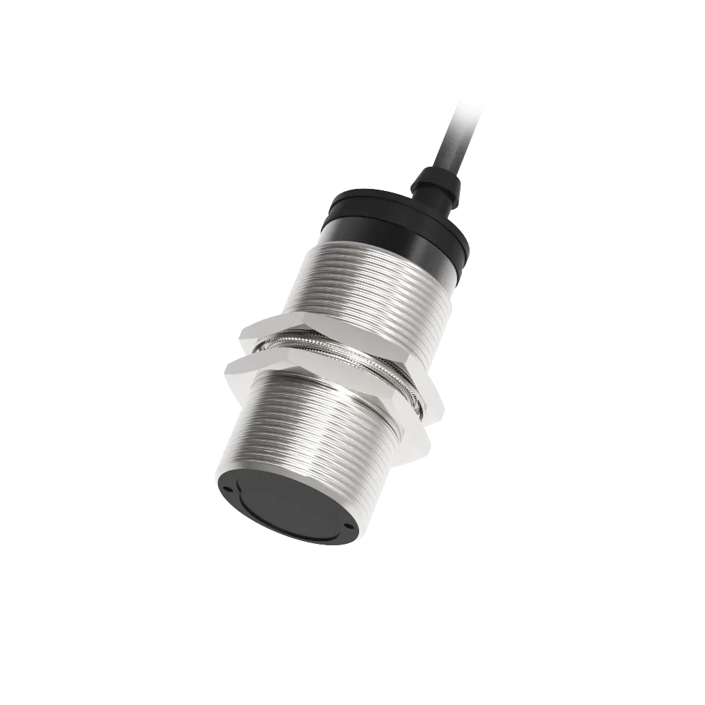
A diffuse sensor puts the emitter and receiver in one housing and reads the light scattered back by the target itself. Nothing is mounted opposite, so installation and wiring stay on one side. Rated ranges run from 110 mm to 6 m in M12, M18, M30 and rectangular housings, with NPN or PNP outputs and IP67 protection.
Reviewed by the SEGMENsensor applications engineering team · Shenzhen, ChinaSpecifications taken from current production selection tablesLast updated:
What is a diffuse photoelectric sensor?
A diffuse photoelectric sensor houses the emitter and receiver in one body. It projects light at
the target and switches its output when enough light scatters back off the target surface. Nothing is
mounted opposite — no receiver, no reflector — which makes it the simplest and cheapest
optical sensor to install.
One housing, one cable. The target itself returns the light, so nothing is mounted opposite.
When is diffuse the right choice, and when is it not?
Diffuse suits short gaps where only one side is accessible and the target is reasonably
reflective. It is the wrong choice in three cases:
Dark or matt targets. Detection depends entirely on how much light comes back.
Matt black cardboard returns a small fraction of what white card returns, so effective range falls
sharply below the rated figure.
A close background. If a machine frame or a second product sits just behind the
target, the sensor may see the background instead. A fixed-distance optic solves this; plain diffuse
does not.
Dust, mist or spray. Light makes a return trip through the contamination, so the
loss is roughly doubled compared with through-beam.
How much does target colour change the range?
Rated diffuse distances are stated against a standard white reference card. Real targets return
less. As a working rule for layout planning, treat glossy white as the rated figure, matt grey as
roughly half, and matt black as a small fraction of it — then verify with a sample. If the
calculation gets close to the rated distance, step up a housing size or move to retro-reflective.
The reduction factors above are planning guidance, not tested values for a specific
target. Send us a sample of the actual material and we will confirm the achievable distance.
What ranges are available?
Housing
Series
Rated range
Typical application
M12 barrel
SEGP12 / SEGB12
200 mm
Small assembly cells, part-in-nest checks
M18 barrel
SEGP18 / SEGB18
150 mm, 500 mm, 1 m
General conveyor presence detection
M30 barrel
SEGP30 / SEGB30
500 mm, 1 m
Wider belts, pallet presence
Rectangular 31 mm
SEGQ31
110 mm – 800 mm, 5 m
Flat mounting, tight side clearance
Rectangular 50 mm
SEGQ50
400 mm – 2 m
Longest diffuse ranges, palletising
Selection table
82 diffuse configurations are available. Models ending in N give an NPN output, P a PNP output;
most are supplied with light-on and dark-on variants.
Model
Series / form
Sensing distance
Output
Supply
Connection
Housing
Light source
SEGB12-D0200N-SI4U2-JP
B12 · M12
200 mm
NPN light-on / dark-on
10-30 V DC
2 m PVC cable
Nickel-plated brass
Infrared
SEGB12-D0200P-SI4U2
B12 · M12
200 mm
PNP light-on / dark-on
10-30 V DC
2 m PVC cable
Nickel-plated brass
Infrared
SEGB18-D0150A-DIEL4
B18 · M18
150 mm
Dark-on
24-240 V AC
M12 connector
Nickel-plated brass
Infrared
SEGB18-D0150A-LIEL4
B18 · M18
150 mm
Light-on
24-240 V AC
M12 connector
Stainless steel / nickel-plated brass
Infrared
SEGB18-D0500N-SIEU4
B18 · M18
500 mm
NPN light-on / dark-on
10-30 V DC
M12 connector
Nickel-plated brass
Infrared
SEGB18-D0500P-SIEU4
B18 · M18
500 mm
PNP light-on / dark-on
10-30 V DC
M12 connector
Nickel-plated brass
Infrared
SEGB30-D0500A-DI3L2
B30 · M30
500 mm
Dark-on
24-240 V AC
2 m PVC cable
Nickel-plated brass
Infrared
SEGB30-D0500A-LI3L2
B30 · M30
500 mm
Light-on
24-240 V AC
2 m PVC cable
Nickel-plated brass
Infrared
SEGB30-D0500N-SI4U2
B30 · M30
500 mm
NPN light-on / dark-on
10-30 V DC
2 m PVC cable
Nickel-plated brass
Infrared
SEGB30-D0500P-SI4U2
B30 · M30
500 mm
PNP light-on / dark-on
10-30 V DC
2 m PVC cable
Nickel-plated brass
Infrared
SEGB30-D1000A-DI3L2
B30 · M30
1 m
Dark-on
24-240 V AC
2 m PVC cable
Nickel-plated brass
Infrared
SEGB30-D1000A-LI3L2
B30 · M30
1 m
Light-on
24-240 V AC
2 m PVC cable
Nickel-plated brass
Infrared
SEGB30-D1000N-SI4U2
B30 · M30
1 m
NPN light-on / dark-on
10-30 V DC
2 m PVC cable
Nickel-plated brass
Infrared
SEGB30-D1000P-SI4U2
B30 · M30
1 m
PNP light-on / dark-on
10-30 V DC
2 m PVC cable
Nickel-plated brass
Infrared
SEGP12-D0200N-SI4U2
P12 · M12
200 mm
NPN light-on / dark-on
10-30 V DC
2 m PVC cable
Plastic
Infrared
SEGP12-D0200P-SI4U2
P12 · M12
200 mm
PNP light-on / dark-on
10-30 V DC
2 m PVC cable
Plastic
Infrared
SEGP18-D0150A-DI3L2
P18 · M18
150 mm
Dark-on
24-240 V AC
2 m PVC cable
Plastic
Infrared
SEGP18-D0150A-LI3L2
P18 · M18
150 mm
Light-on
24-240 V AC
2 m PVC cable
Plastic
Infrared
SEGP18-D0500N-SIEU4
P18 · M18
500 mm
NPN light-on / dark-on
10-30 V DC
2 m PVC cable
Plastic
Infrared
SEGP18-D0500P-SI4U2
P18 · M18
500 mm
PNP light-on / dark-on
10-30 V DC
2 m PVC cable
Plastic
Infrared
How do you wire a diffuse sensor?
Photoelectric sensor wire colour and connector pin assignment
Function
Cable colour (IEC 60947-5-2)
M12 pin
M8 pin
Notes
Supply +
Brown
1
1
10–30 V DC on standard DC models
Supply −
Blue
3
3
0 V / common
Output (NPN or PNP)
Black
4
4
Main switching output
Second output / mode select
White
2
2
Present on 4-wire NO + NC and selectable models
Emitter (through-beam)
Brown + blue only
1, 3
1, 3
Emitters carry no switching output
An NPN output sinks current to 0 V; a PNP output sources current from the supply. Match the sensor
output to the input card of the controller — wiring a PNP sensor to a sinking input (or the reverse) leaves the
input permanently off. Confirm the pin assignment on the datasheet before wiring a specific model.
Troubleshooting diffuse installations
Symptom
Likely cause
What to check
Output never switches
Output type does not match the controller input
NPN vs PNP; sinking vs sourcing input card
Output chatters at the switching point
Insufficient excess gain, or target at the edge of range
Move the target closer, or step up to a longer-range model
Dark targets are missed
Diffuse mode reflectivity too low
Switch to retro-reflective or through-beam
Shiny or mirrored targets are missed
Specular reflection steered away from the receiver
Tilt the sensor 10–20° away from perpendicular to the surface, or use through-beam
Clear bottles or film not detected
Standard optics pass straight through the target
Use a polarising-filter retro-reflective model
Random switching near other sensors
Optical crosstalk between adjacent units
Alternate emitter/receiver orientation, or increase spacing
Detection drifts through the shift
Lens contamination in dust or spray
Clean the lens; move to through-beam for a higher signal margin
Fast parts on a conveyor are skipped
Response time too slow for the line speed
Calculate dwell time from part length and belt speed, then compare with response time
Output inverted versus expectation
Light-on / dark-on set the wrong way
Select the opposite model variant, or switch mode if the model supports it
Related products
Photoelectric sensing is one of six sensor families we build in Shenzhen. Where an optical
solution is not the right fit, these alternatives cover the same detection tasks:
A diffuse photoelectric sensor combines emitter and receiver in a single housing and detects an object by the light that scatters back off its surface. No reflector or opposing receiver is needed, so it mounts and wires from one side only, which makes it the simplest optical sensor to install.
What is the maximum range of a diffuse sensor?
In this catalogue diffuse models are rated from 110 mm to 6 m, with most falling between 200 mm and 1 m. Rated figures assume a standard white reference target; darker and matt surfaces return less light and reduce the usable distance.
Why does my diffuse sensor miss dark objects?
Because detection depends on reflected light. A matt black surface returns only a small fraction of the light that a white reference card returns, so the received signal can fall below the switching threshold. Move to retro-reflective or through-beam sensing, where target colour has far less influence.
What is the difference between diffuse and retro-reflective?
A diffuse sensor relies on the target to return light; a retro-reflective sensor relies on a dedicated reflector and detects the target when it interrupts that return path. Retro-reflective gives longer range and far less sensitivity to target colour, at the cost of mounting a reflector opposite.
Can a diffuse sensor ignore the background behind the target?
Plain diffuse models cannot reliably distinguish a target from a background close behind it. Fixed-distance and background-suppression optics are designed for that situation. Tell us the gap between target and background and we will confirm which option applies.
Does ambient light affect diffuse sensors?
The light source is modulated and the receiver is tuned to that modulation, which rejects most ambient light. Very strong direct sunlight or a high-frequency lamp aimed into the lens can still interfere. Shielding the lens or reorienting the sensor normally resolves it.
What supply voltage and output do these sensors use?
Standard models run on 10–30 V DC with an NPN or PNP transistor output, matching the 24 V DC control panels used on most machinery. Cable versions ship with a 2 m PVC lead; M8 and M12 connector versions are also available.
How do I mount a diffuse sensor against a shiny target?
Angle the sensor 10–20° away from perpendicular. A polished surface reflects light specularly, like a mirror, so a perpendicular mounting sends the beam straight back off-axis or floods the receiver. A slight tilt produces a more stable, repeatable signal.
Do you offer diffuse sensors for OEM and private label?
Yes. SEGMENsensor supplies photoelectric sensors to OEM customers from 10 pieces per configuration, with custom cable length, connector type, housing marking and output configuration. Paid samples of catalogue models normally ship within five to seven working days.
What do you need from me to recommend a diffuse model?
The target material, colour and surface finish; the sensing distance; the distance from target to any background behind it; the mounting space and thread size available; and the controller input type. A photograph of the installation point is usually more useful than a written description.
OEM and private-label supply
SEGMENsensor manufactures photoelectric sensors in Shenzhen for industrial OEM customers and
distributors. Tell us the detection task rather than a part number — target material and colour,
distance, background, mounting space, environment and controller input type — and our engineers
return two or three suitable configurations with drawings.
MOQ from 10 pieces
Standard catalogue models ship from stock. Custom builds start at 10 pieces per configuration.
Private label and custom marking
Housing colour, laser marking, label artwork and packaging can be produced to your specification.
Cable and connector options
Cable length, jacket material, M8 or M12 connector and pin assignment can be changed on request.
Samples in 5–7 working days
Paid samples of catalogue models normally leave Shenzhen within five to seven working days.
Send us the detection task
Target, distance, background, environment and controller input — we reply with specifications
and a quotation within one working day.